Design, Test and Measurement
In the laboratory, services on design, test and measurement are provided to universities, public and private institutions with various software (e.g., SolidWorks®, Solidcam®, CutPro®, Magics®, Matlab®, Tracecut® etc.) and equipment. Research and development studies on the aforementioned areas can be also carried out by means of the equipment and their corresponding software. They are given as follows:
 |
|
The equipment used for the abovementioned studies are given below in detail...
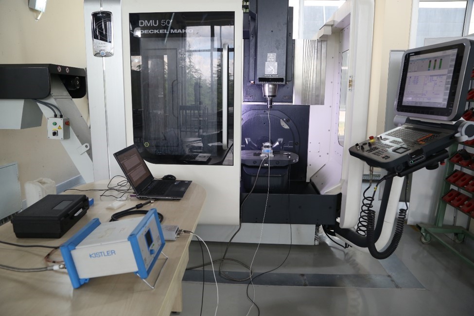
In machining operations, cutting forces arise due to the nature of the cutting process. These forces are of great importance with regards to machine power, tool design, workpiece quality, fixture design, etc. Therefore, it is necessary to measure the cutting forces during machining operations and evaluate their variation depending on many different factors e.g. the cutting parameters, cutting tool geometry, workpiece material, cooling system etc. In addition, it is required to measure the cutting forces in the verification studies of the cutting forces predicted by various modeling methods (analytical, numerical, mechanistic). Dynamometers are widely used for these purposes. Cutting forces can be measured in milling and turning operations in our laboratory with the dynamometer whose technical specifications are given below. CutPro® is used as data acquisition software.
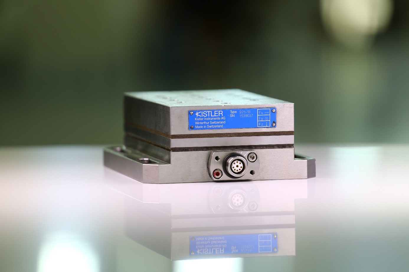 |
Technical Specifications: Measurement Range (Fx Fy Fz): -5…5 kN Operating temperature range: 0-70 °C Weight: 7.3 kg |
In order to measure the dynamics or frequency response function of a system or structure, a force with a certain frequency bandwidth should be applied to the system and the applied force must be measured simultaneously. This force can be applied in various ways. Excitation of the system by applying a force with an instrumented hammer is a commonly used method.
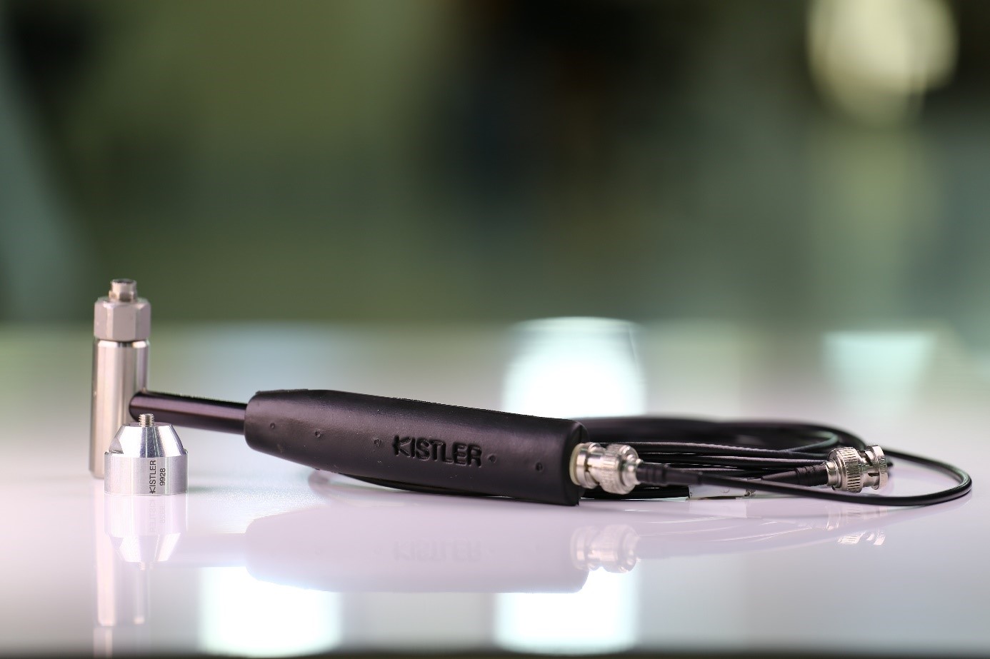 |
Technical Specifications Force range: 0-2000 N Overload capacity: 500% Resonant frequency: 27 kHz Weight (Hammer Head): 100 gr Operating temperature range: -20…70 °C |
The response of the system excited by the applied force can be measured via an accelerometer. The frequency response function of the system can be obtained by dividing the response of the system measured by the accelerometer with the force applied-measured by the hammer in the frequency domain. Generally, machine/spindle-tool holder-tool system and workpiece frequency response function measurements are performed in our laboratory. In these measurements, CutPro®-MALTF module is used. Besides, the accelerometer can be employed for a real time monitoring of cutting process.
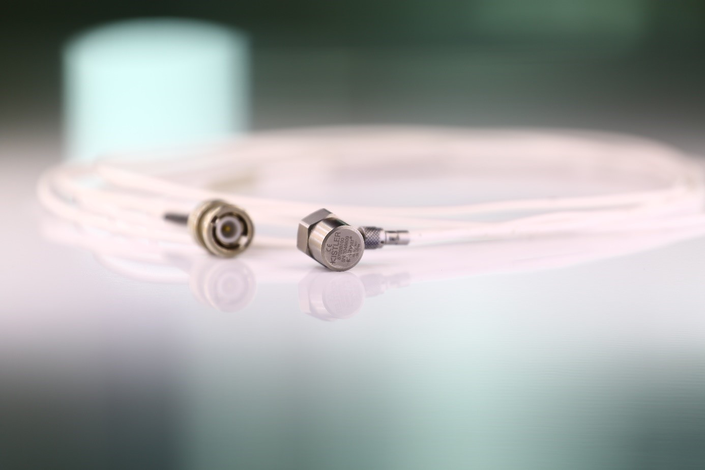 |
Technical Specifications (8702B500 and 8702B100, respectively): Acceleration range: ± 500 g and ± 100 g Sensitivity: 10.13 mV/g and 50.13 mV/g Operating temperature range: -54…120 °C |
CCD Laser Displacement Sensor (Keyence LK-G87)
Laser Displacement Sensor is widely used in many processes such as:
- Thickness inconsistency measurements,
- Plate thickness measurements and detecting variations in the thickness,
- Vibration measurements,
- Measuring the balance of rotating parts e.g., disc, cutting tool, etc.
- Height checking during the welding process,
- Frequency response function measurements
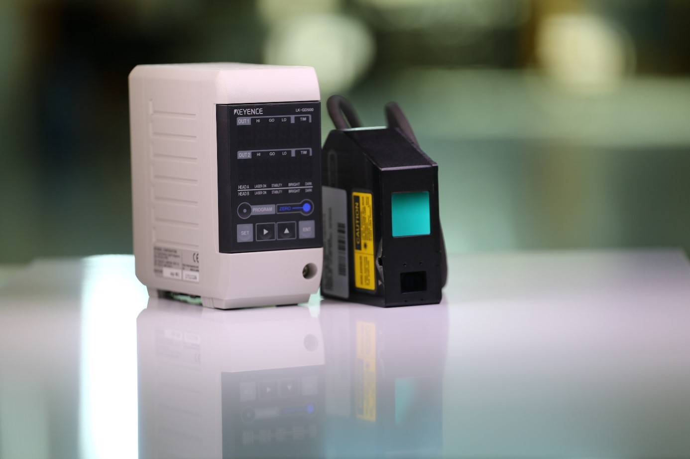 |
Technical Specifications: Measurement range: ± 15 mm Repeatability: 0.2 µm |
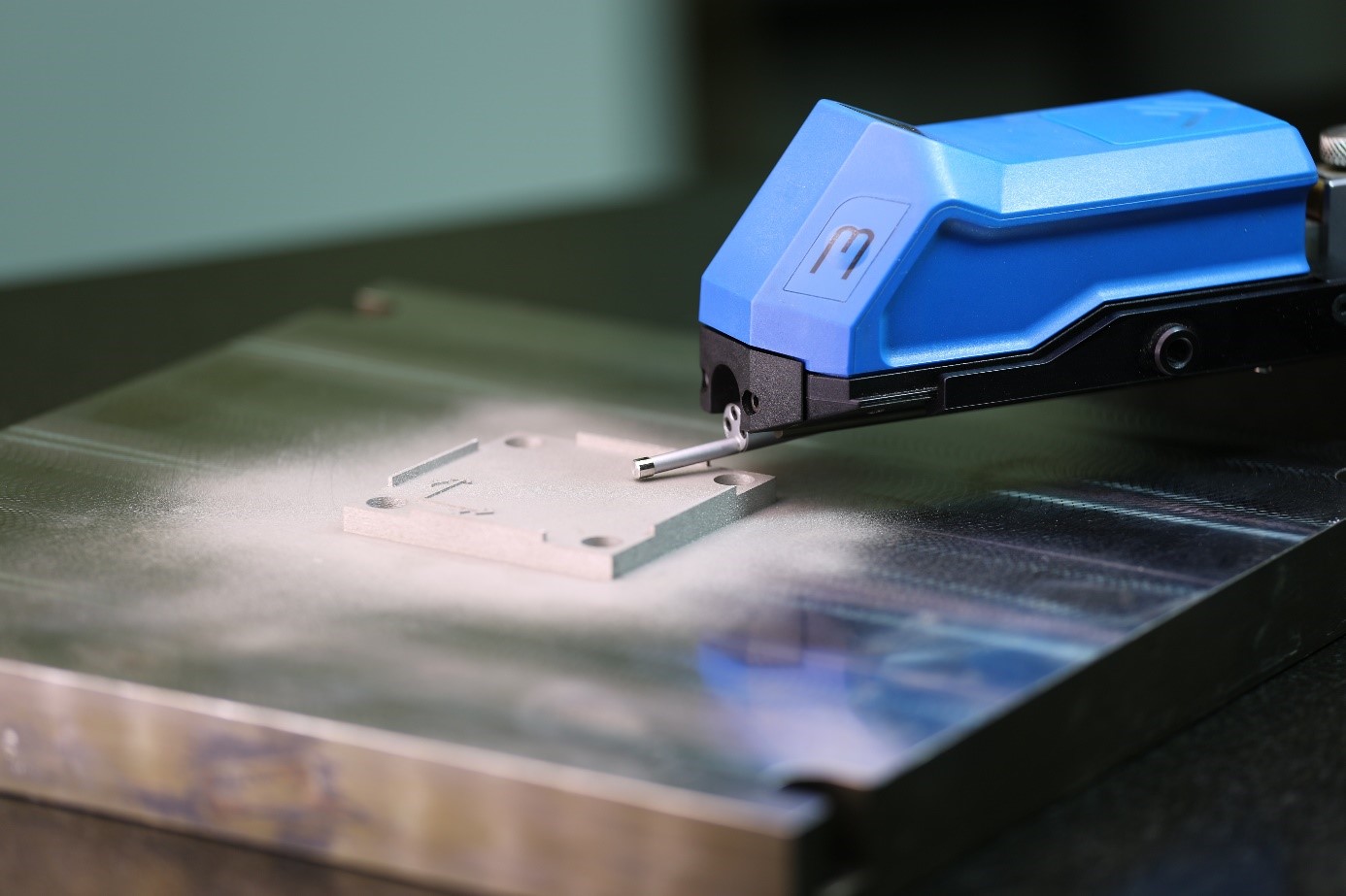
It is possible to precisely obtain the 3D geometry data of a manufactured part with 3D scanning devices. Solid model of the part is achieved by processing of this data through various data processing methods. In general, 3D scanning devices are widely used in quality inspection of the manufactured parts and reverse engineering applications.
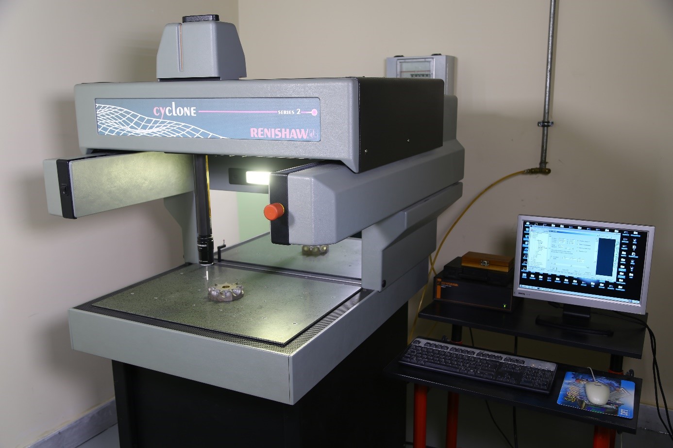 |
Technical Specifications: Working dimensions: 600 mm x 500 mm x 400 mm Accuracy: 50 µm Scanning speed: Maximum 3 m/min Rapid speed: 6 m/min Scanning rate: 140 points/sec Prob type: Renishaw 3 axis SP620 analogue scanning prob Maximum workpiece weight: 200 kg Software: Renishaw Tracecut |
Workpiece surface quality is of great importance in the manufacturing industry. After the manufacturing processes, an inspection of the surface quality may be performed with surface profilometers.
 |
Technical Specifications: Surface Roughness Parameters: Ra, Rz, Rmax Memory: Maximum 125 measurements Traverse length (in accordance with ISO 4287): Lt = 1.5 mm, 4.8 mm, 15 mm Traverse speed: vt = 0.15 mm/s, 0.5 mm/s, 1 mm/s Accuracy class: Class 1, in accordance with DIN 4772 Minimum display Value: 0.01 µm |
|
|
Heat treatment is basically controlled heating and cooling of materials at certain temperature ranges. By doing so, it is possible to obtain different microstructures and mechanical properties in materials. In general, the materials are gained the desired mechanical properties by applying annealing and hardening heat treatments.
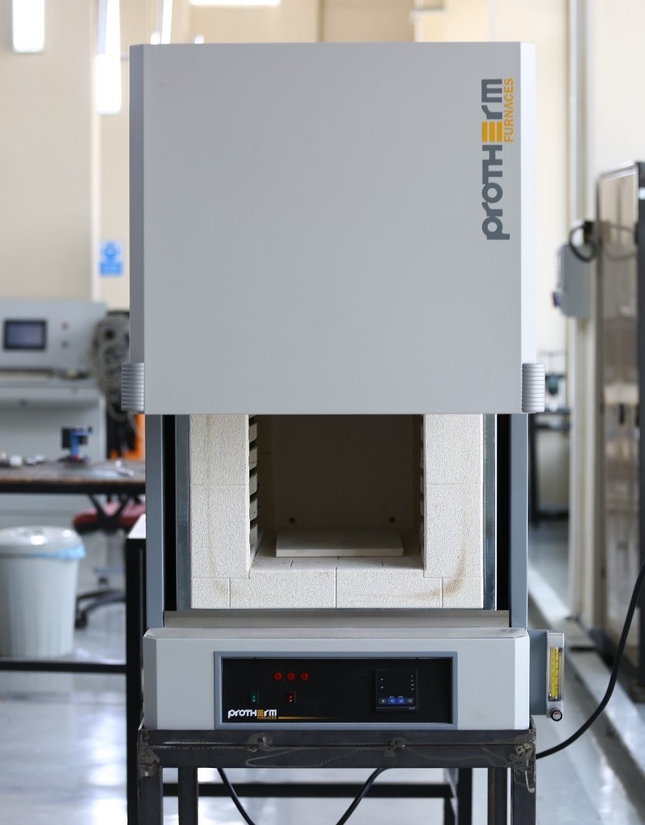 |
Technical Specifications: Chamber size: 30 cm x 30 cm x 50 cm Volume: 45 L Maximum temperature: 1100 °C Time for reaching maximum temperature: 60 min Maximum power: 6 kW Temperature deviation: ± 2 °C |
Milling cutters can be attached to holders with different clamping mechanisms such as collet, hydraulic, shrinkfit etc. The shrinkfit tool holders provide minimum run-out in mounting of cutting tools.
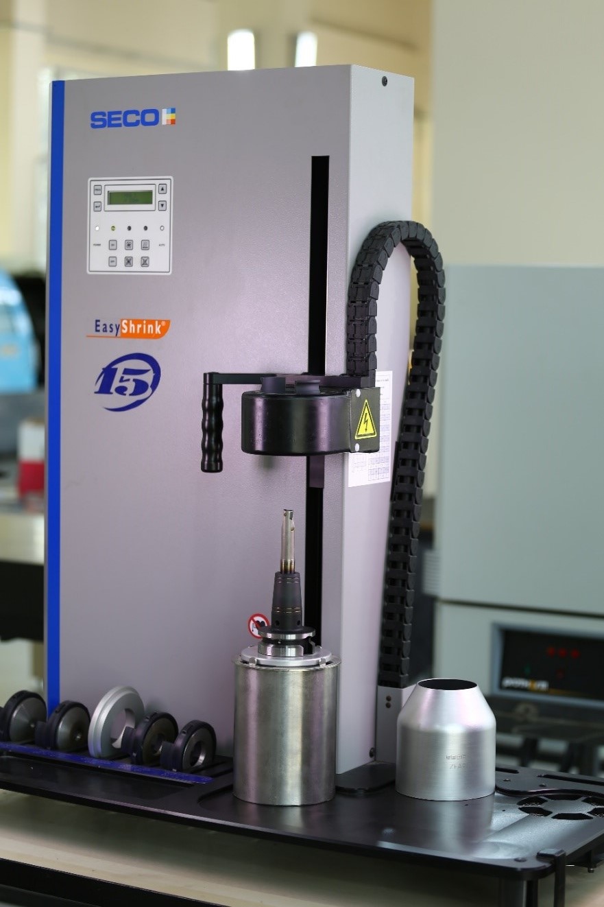 |
Technical Specifications: Capacity: 3 to 32 mm for carbide and heavy metal tool shanks, 6 to 32 mm for steel and HSS tool shanks Shrinking time approx.: 10 sec |
Tool wear resulting from various milling and turning operations can be examined with the microscope having a 2MP 0.5x camera.
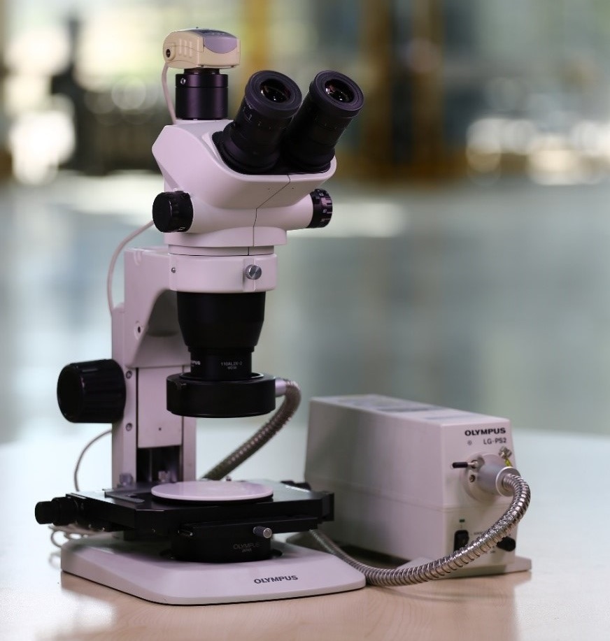 |
Technical Specifications: Magnification: 0.67x….4.5x Magnification ratio: 6.7:1 Coarse handle stroke: 110 mm Webcam compatibility: 2MP with 0.5x camera |
Today, thermal cameras are widely used in defense, electrical-electronic and many engineering applications. Besides, thermal cameras are employed in monitoring the manufacturing processes (such as measuring the cutting temperature in machining operations, detecting the temperature of the layers in the additive manufacturing process, etc.). By means of temperature maps provided by them, studies on fault detection and prevention, parameter optimization (especially in manufacturing processes) and increasing process efficiency can be carried out.
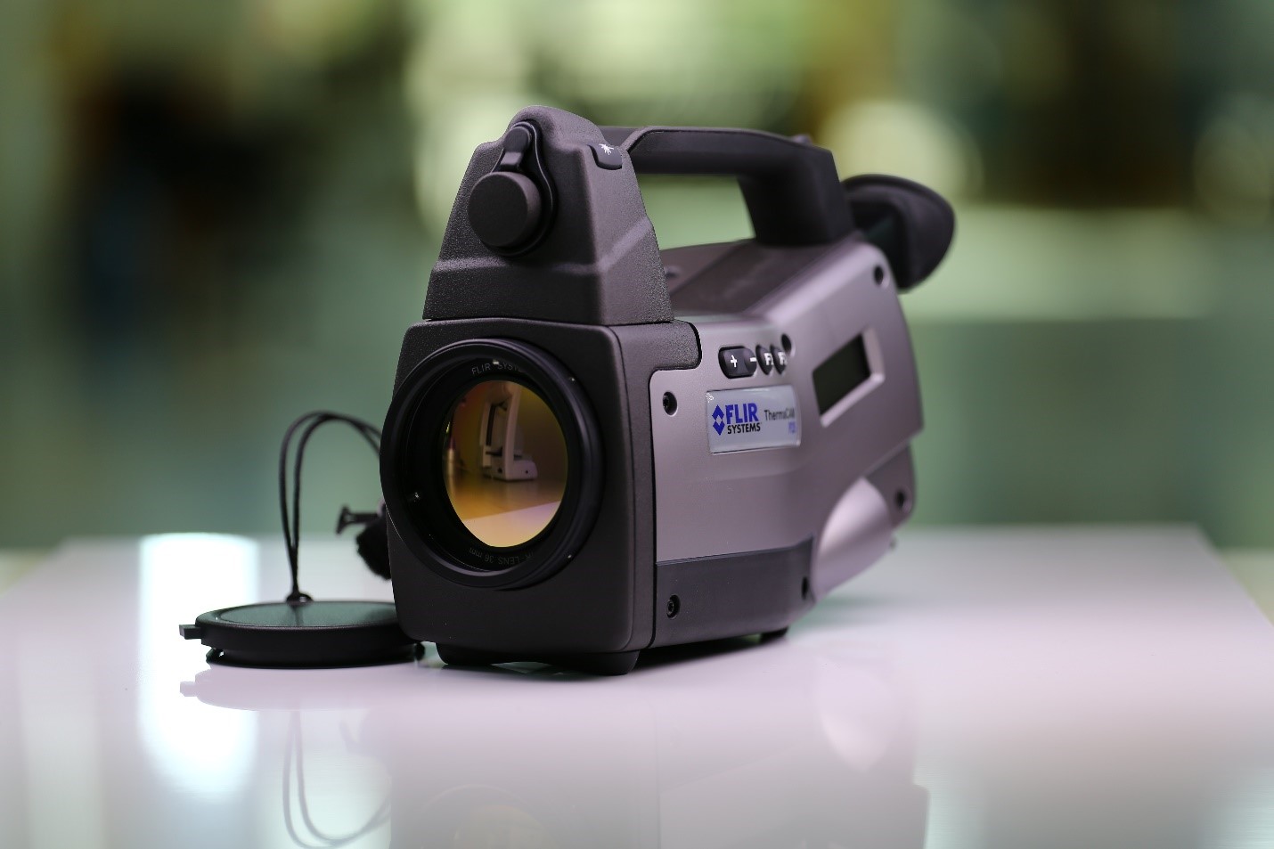 |
Technical Specifications: Temperature measurement range: -40…..+500 °C Accuracy: ± 2 °C Imaging frequency: 50/60 Hz Thermal sensitivity @ 50/60Hz: 0.08 °C at 30 °C |